Batteries have a safe voltage range to use, the highest and lowest voltage is generally known as the charge and discharge termination voltage or cut-off voltage, when the actual working voltage of the battery for a long time is lower than the discharge termination voltage or a long time is higher than the charging termination voltage, irreversible damage will occur inside the battery, serious damage to the battery, resulting in performance decline, commonly known as battery attenuation, The performance of battery attenuation is that the internal resistance of the battery increases, the capacity decreases and so on.
Therefore, there is generally a small PCB board inside the lithium-ion battery, which is packaged together with the battery, as shown in the figure below. The main function is to protect the battery.
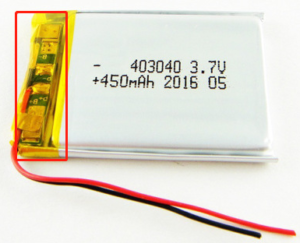
Depending on the circuit composition, the circuit board generally has over discharge protection, over charge protection, over current protection, short circuit protection and FUSE protection after the failure of the control IC. The working principle of these protection will be explained with a common circuit below.
A, lithium battery protection board composition
A general lithium battery protection board consists of a control IC, a MOS tube, a resistance capacitor, and a FUSE, as shown in the following figure.
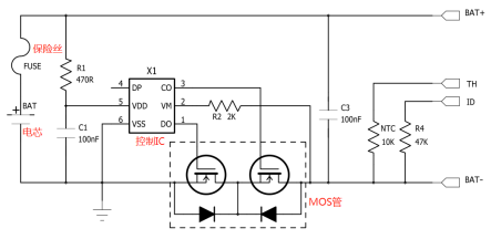
TH is temperature detection, inside is a 10K NTC connected to the negative electrode of the battery; ID is the battery in position detection, generally 47K/10K resistance to the resistance negative terminal, some 0R resistance; TH and ID are optional and not available in all lithium batteries.
Overcharge protection
When the battery is charged, current (as indicated by the arrow) flows from the positive side of the battery pack, passes through FUSE, and flows out of the negative side. The two MOS tubes at the bottom are both on.
TH is temperature detection, inside is a 10K NTC connected to the negative electrode of the battery; ID is the battery in position detection, generally 47K/10K resistance to the resistance negative terminal, some 0R resistance; TH and ID are optional and not available in all lithium batteries.
1. Overcharge protection
When the battery is charged, current (as indicated by the arrow) flows from the positive side of the battery pack, passes through FUSE, and flows out of the negative side. The two MOS tubes at the bottom are both on.
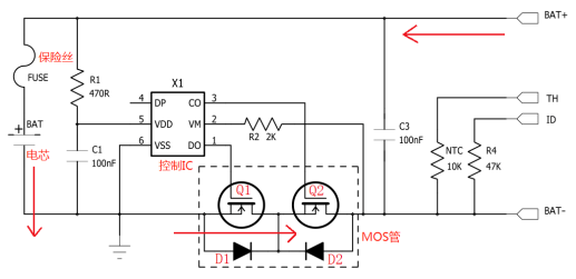
The direction of current when the battery is charged is shown by the arrow
When charging, control IC X1 will always monitor the voltage between the fifth pin VDD and the sixth pin VSS, when the voltage is greater than or equal to the overcharge cut-off voltage and meet the overcharge voltage delay time, X1 will control the third pin to close the MOS tube Q2, Q2 is closed, the charging loop is cut off (Q2 body diode D2 is reverse cut-off), At this point, the battery can only discharge.
Discharge conditions of overcharge protection (meet one) :
(1) The voltage at both ends of the cell drops to the overcharge recovery voltage of the protection IC;
② Add load discharge to the output end of the battery pack, and discharge to a voltage less than the overcharge protection voltage.
2, over put protection
When a load is added to both ends of the battery pack and discharged, the current (as indicated by arrows) is opposite to the charge, as shown in the figure below.
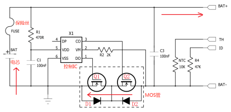
Discharge, control IC X1 will also monitor the voltage between the 5th pin VDD and the 6th pin VSS, when the voltage is less than or equal to the over release cut-off voltage and reach the over-release voltage delay time, control IC X1 will pass the first pin off Q1, Q1 is closed after the discharge loop is cut off (Q1 body diode D1 is reverse cut-off), this time, Batteries can only be charged.
Over discharge protection release condition: remove the load, charge the battery pack, when the voltage between VM-VDD reaches the value of over discharge recovery voltage, control IC X1 will reopen the MOS tube Q1.
3, over current protection/short circuit protection
Over current protection refers to the over discharge current protection, general control IC has over current protection and short circuit protection of two kinds, control IC time monitoring VSS-VM voltage value, when the voltage value reaches the threshold of over current protection or short circuit protection and meet the delay time, control IC will MOS tube Q1 off, cut off the discharge circuit.
When a battery discharges, the current direction is shown by the arrow
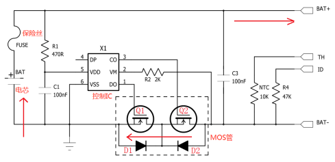
The condition of over current protection removal is: the output load is removed, the control IC will automatically turn Q1 on again.
The voltage value of over current protection is generally 0.1-0.2V, and the voltage value of short-circuit protection detection is generally 0.9V~2V. These two values are related to the control IC. Different IC, these two values are not the same.
Short-circuit protection voltage value refers to the on-voltage drop of the current flowing through Q1 and Q2, that is, it can be concluded that the larger the on-internal resistance of the MOS tube, the smaller the protection current value. For example, if the MOS tube with internal resistance of 20mΩ is used as the control IC with over current value of 0.15V, the current of over current protection should
be: 0.15V/(0.02*2)=3.75A.
4, control the FUSE protection after IC failure
Some protection board inside will add fuse, after the control IC failure, play a secondary protection role, to avoid worse results, of course, will also increase the cost.
*Statement: This article is reproduced from the network, the content is for reference only, in case of infringement, please contact ktechenergy.
